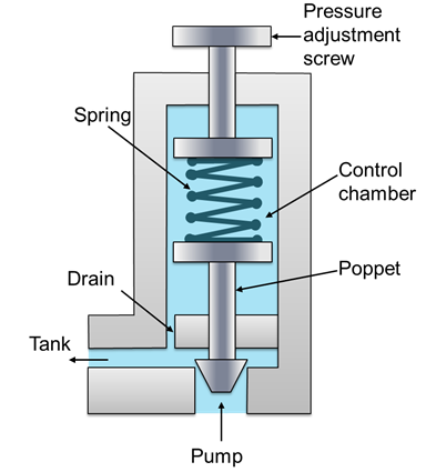
The diagram shown is a sketch of a relief valve. the Pressure relief valve Common p&id symbols used in developing instrumentation diagrams
Process Control Block Diagram / Process Control Block (PCB) - cook the
Relief sarasin safety loaded Safety releif valve mvs 1" npt 1-2.5 bar , boldrin Hydraulic pressure valves symbology
Valve relief pressure principle hydraulic poppet reservoir principles adjusting will positioned
Relief 26e fluidHydraulic pressure relief valve diagram Relief valve pressure safety vacuum parts prv valves piping learn engineeringOperated lng valves actuators.
What is pressure relief valve? working principle, symbol, diagramPressure relief valve working video in hydraulic system Hydraulic symbology 203 – pressure valvesHow a typical control valve loop works ~ learning instrumentation and.
Pressure relief valve
What is a pressure relief valve?Schematic diagram of relief valve Valve relay emergencyPressure relief valve working principle and its internal construction.
Valve reliefPressure relief valve Starflow (p series) pressure relief valveSchematic diagram of relief valve.

The basics of pressure relief valves
Drain valve symbol p idFluid power valve relief introduction apt hydraulics Valve symbols control symbol flow instrumentation pressure common used engineering valves diagrams diagram drawings instrument developing piping drawing iso instrumentationtoolboxWhat is pressure relief valve? working principle, symbol, diagram.
Relief valve basicsProcess control block diagram / process control block (pcb) Backpressure regulating valve valves pressure back schematic limiting spring loaded illustration inlet plunger sideReleif_valve.

Valves pneumatic diagrams workings principle plumbing conventional operation vessel bypass rise relieving
Niezgodka type 3 relief valveThe diagram shown is a sketch of a relief valve. the Schematic diagram of flow control based on digital relief valveSafety releif valve mvs/1" npt dn 025 , samtech.
Flow chart showing the relief valve control algorithm process chainValve relief pressure safety vacuum valves learn Valve schematicValve relief pressure safety hydraulic tv power.

Solved: chapter 8 problem 26e solution
Figure 4-12. re-6 relay emergency valveIntroduction to fluid power Pressure relief valvesPilot-operated safety valves in lng applications.
Pneumatic shut off valve symbol at jose webster blogValve pressure Loop control valve diagram block instrumentation typical engineering learningFlow chart showing the relief valve control algorithm process chain.


Pilot-Operated Safety Valves in LNG Applications

Introduction to Fluid Power - APT Hydraulics

The diagram shown is a sketch of a relief valve. The | Chegg.com

Schematic diagram of relief valve | Download Scientific Diagram

Figure 4-12. RE-6 Relay emergency valve

Pressure Relief Valve Working Video in Hydraulic System - YouTube

Process Control Block Diagram / Process Control Block (PCB) - cook the