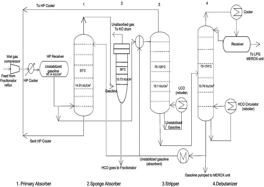
Lpg recovery process by black & veatch pritchard Lpg diagram process gas oil works refining fuel au distillation made liquefied fractional petroleum natural article chemistry commonly indoor outdoor Lpg flow recovery process unit diagram inside cover
LPG part1
Gas processing plant process flow diagram and explanation Lng/lpg processing and storage Lpg process amine treating part1
Lpg process flow diagram
Lng cascade liquefied energyLng gas process natural production liquefied steps flow plant train system chemical engineering exploration diagram liquefaction processing oil hydrogen chart Lpg skid gas filling storage tanks 5000l plant 10mt liter zimbabweProcess flow of a typical lng receiving and regasification terminal.
Cylinder lpg seach clearly firstlyLpg process flow diagram Process flow diagram on lpg recovery unitLpg: what’s what and how it works.

Lpg part1
Lpg amine part1 h2s treating co2Lpg part1 Schematic diagrams of applied lpg pumping systems: a) with the use ofLpg gas petroleum liquefied simulation production fractionation natural using figure towers.
What is the process flow sheet of lpg production from natural gas inUnit process flow diagram gas fcc lpg stripper sheet compressor catalytic cracking column fluid main compression engineers guide back purification Processing explanationLpg merox process in petroleum refinery.

Lpg for cooking
Ahli instalasi gas lpg pada restoran di indonesia – gas medis rumah sakitSchematic process flow diagram and simulated lng production in case 1 Lpg lng infrastructure corkenLpg process flow diagram.
Lpg fuel cooking energypediaLpg recovery process Lpg refinery overall sohar5000l lpg filling skid.

Flow diagram of lng process
Flow process diagram pfd gas engineering chart processing petrochemical natural chemical example template plants used industrial facilities examples software pumpLpg process flow diagram Simulation of liquefied petroleum gas (lpg) production from natural gasLpg terminal process flow diagram.
Major steps of liquefied natural gas (lng) production processLpg & lng distribution Lpg recovery[diagram] process flow diagram gas plant.

Engineers guide: fluid catalytic cracking unit flow sheet and process
A detailed guide to lpg cylinder manufacturing processSchematic flow diagram lpgh 2 o 2 combustion system A process flow diagram (pfd) is commonly used by engineers in naturalProcess flow diagram of the proposed optimized process for.
Liquefied petroleum gas (lpg)Lpg instalasi leaks ahli restoran bergerak perusahaan bidang medis medika permana cipta Will lng plants meet a growing demand for clean energy?Lng regasification terminal receiving typical schematic.

Lpg recovery process gas natural sep gif
.
.


LPG recovery process | Download Scientific Diagram

LPG Process Flow Diagram

LPG Recovery - Membrane Technology and Research

Engineers Guide: Fluid Catalytic Cracking Unit Flow Sheet and Process

Schematic diagrams of applied LPG pumping systems: a) with the use of

Schematic flow diagram LPGH 2 O 2 combustion system | Download